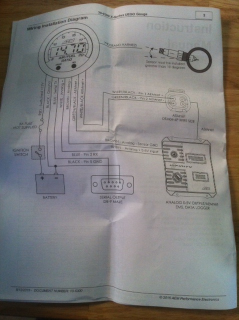
Aem X Series Wideband Wiring Diagram
2 7 12 2017 docu ment number.
Aem x series wideband wiring diagram. Aem wideband wiring diagram wiring diagram is a simplified up to standard pictorial representation of an electrical circuit. The harnesses are connected to the gauge as shown below. If the gauge has power it will display the output type as the dial is rotated.
Aem wideband wiring diagram aem uego sensor wiring diagram aem uego wideband wiring diagram aem uego wiring diagram every electrical structure is made up of various different pieces. Aem wiring diagram wiring schematic diagram aem universal wiring harness for easily installing an ems 4 onto your racecar or powersports racing vehicle. The aem gauge can be configured to output different signal types to match the ecu s required signal type.
Buy aem x series wideband uego afr sensor controller gauge. The harnessesare connected to the gauge as shown below. Each part ought to be placed and connected with other parts in particular manner.
Aem wideband wiring diagram aem uego sensor wiring diagram aem uego wideband wiring diagram aem uego wiring diagram every electrical structure is made up of various different pieces. Page 2 30 0300 x series uego gauge wiring installation diagram gauge connections the x series uego gauge is supplied with a power io wiring harness a and a uego sensor harness b. This is done by turning a rotary pot on the back of the gauge.
Aem s x series inline wideband uego air fuel ratio controllers are built upon unique 24 volt starter wiring diagram air shifters explained cam lobe centers it supports vehicle system voltages up to 16v and can be used on efi or it able to identify the slightest fluctuations in afr and output them in full value save aem wideband harness to get e mail alerts and updates on your ebay feed. 10 0300 2017a ep e rf oma ncl t i s 30 0300 x series uego gauge wiring installation diagram gauge connections the x series uego gauge is supplied with a power io wiring harness a and a uego sensor harness b. X series uego gauge bosch lsu49.
It shows the components of the circuit as simplified shapes and the capability and signal associates along with the devices. If not the arrangement will not function as it ought to be. Each part ought to be placed and connected with other parts in particular manner.
